A ship mooring system is not simply a collection of ropes between a vessel and a quay. It is an engineered restraint system in which line leads, material properties, winch brakes, deck fittings, environmental loads and human decisions must work together. When one part is misunderstood, the result can be equipment damage, a breakaway or a fatal line-of-fire accident.
This guide explains a conventional alongside mooring arrangement for merchant ships. It is educational, not vessel-specific. The ship’s approved mooring arrangement, safety management system, manufacturer instructions, terminal requirements and the officer in charge always take precedence.
What Is a Ship Mooring System?
A ship mooring system is the complete arrangement used to hold a vessel at a berth or other fixed location. It includes the mooring lines, tails and joining arrangements; winches and their brakes; bitts, bollards, chocks, fairleads and rollers; shore bollards or quick-release hooks; and the procedures used to plan, operate, inspect and maintain the system.
The objective is not to make the ship completely immovable. The system must limit vessel movement to an acceptable range while keeping loads within the safe capability of the lines, winches, fittings and shore equipment. Some elasticity is necessary because a perfectly rigid system would transfer dynamic loads directly into equipment and supporting structure.
A good arrangement distributes load across lines with compatible strength and elasticity. A poor arrangement can leave one short or badly led line carrying a disproportionate share while neighbouring lines remain comparatively lightly loaded.
The Forces a Mooring Arrangement Must Control
A vessel alongside is exposed to forces that change continuously. Wind acts on the above-water profile, current on the underwater hull, and waves or swell can produce repeated movement. Passing ships may create surge or suction. Cargo operations change draft and freeboard, while tide changes the vertical relationship between ship and quay.
Longitudinal movement ahead or astern along the berth. Spring lines provide the principal restraint against surge.
Transverse movement toward or away from the berth. Breast lines provide the most direct transverse restraint.
Rotation of the vessel around a vertical axis. The combined forward and aft arrangement helps control the bow and stern.
Heave, roll and pitch also affect line geometry and load. That is why a mooring plan must consider the vessel, the berth and the expected environmental conditions together rather than treating every port call as the same operation.
Typical Alongside Mooring Arrangement
What Each Mooring Line Does
| Line | Typical lead | Primary function | Operational note |
|---|---|---|---|
| Head line | From the forward station to a shore point ahead of the bow | Checks movement astern and contributes to longitudinal restraint | A very steep or short lead can reduce its useful longitudinal component. |
| Stern line | From the aft station to a shore point abaft the stern | Checks movement ahead and contributes to longitudinal restraint | Its condition and load require attention when propulsion or passing traffic affects the stern. |
| Breast line | As close as practical to perpendicular to the ship’s centreline | Restrains transverse movement away from the berth | Short breast lines can experience rapid load changes with tide or vessel movement. |
| Forward spring | From a forward shipboard station to a shore point farther aft | Checks forward surge along the quay | Sometimes called a back spring; terminology must be confirmed during the briefing. |
| Aft spring | From an aft shipboard station to a shore point farther forward | Checks astern surge along the quay | Its lead may cross the forward spring when viewed from above. |
Line names are functional. They do not identify the material, diameter or strength of the rope. A vessel may use several lines of each function, and the exact pattern can vary widely between a bulk carrier at a conventional quay, a tanker at a specialised terminal and a ro-ro vessel at a linkspan.
The Equipment Behind the Lines
Provides controlled heaving, paying out and holding. Its brake is a safety-critical part of the restraint system, not merely a parking device.
Stores or works the line. Split-drum and undivided-drum arrangements require different operating and spooling practices.
Strong securing fittings supported by deck structure. Shipboard fittings are commonly described as bitts; shore fittings are commonly bollards.
Control the line’s route from the deck toward the berth. The lead must avoid damaging contact, excessive angles and unintended escape paths.
Change line direction and reduce friction, but they also alter the potential recoil path if the line parts or jumps free.
Complete the ship–shore system. Terminal fitting capacity, geometry and condition are as important as the equipment on board.
Every fitting creates a load path into the ship or quay structure. An apparently stronger replacement line does not automatically make the system safer: if its strength or elasticity is incompatible with the design, the next weakest component may become the winch brake, a fitting or its supporting structure.
Mooring-Line Materials
Modern merchant ships use synthetic fibre lines, steel wire ropes or combinations involving synthetic tails. Material choice influences strength, elasticity, weight, water behaviour, abrasion resistance, handling and recoil characteristics.
| Material family | Typical characteristic | Important consideration |
|---|---|---|
| Polyamide / nylon | High elongation and energy absorption | Stored energy and snap-back behaviour require careful management; wet properties differ from dry. |
| Polyester | Good abrasion resistance with more moderate stretch | Condition must still be assessed for glazing, internal damage, contamination and wear. |
| Polypropylene | Lightweight and buoyant | Grade, construction and ageing matter; generic material names do not establish safe capacity. |
| HMPE | Very high strength-to-weight ratio and low elongation | Low stretch changes load sharing and dynamic response; approved tails or system design may be required. |
| Steel wire | High strength with low elasticity | Often used with synthetic tails to provide elasticity; lubrication, corrosion, broken wires and end terminations require control. |
Lines performing the same function should have compatible characteristics so they share load effectively. Mixing materials with very different elasticity can cause the stiffer line to take load first. The approved mooring plan, line certificates, manufacturer guidance and the vessel’s Line Management Plan should govern selection and deployment.
Ship Design MBL, LDBF and WLL
Strength terminology has caused confusion in the industry. OCIMF’s Mooring Equipment Guidelines, Fourth Edition—MEG4—introduced a more structured language, particularly for tanker and terminal operations.
The design reference used to establish the required strength relationships of mooring lines, winches and fittings.
The declared minimum break force of a new line when tested according to the applicable method.
The maximum load to which the line should be exposed in service within the defined operating framework.
MEG4 states that Line Design Break Force should normally be within 100–105% of Ship Design MBL and that mooring-winch brake rendering should be set to 60% of Ship Design MBL. The intention is for the brake to render before higher-capacity system components fail, while remaining above the line’s Working Load Limit.
MEG4 is influential industry guidance, especially in tanker trades. Actual settings and limits must come from the ship’s approved data, brake test records, manufacturer instructions, class or flag requirements, company procedures and terminal criteria.
Brake holding capacity also deteriorates if brakes are poorly maintained, contaminated, incorrectly adjusted or never tested under a controlled procedure. A brake rendering at an unknown load is not a reliable protective device.
Snap-Back Is Not the Only Line-of-Fire Hazard
A loaded mooring line stores energy. If it parts, its ends may recoil rapidly. If it slips from a fitting or jumps out of an open roller fairlead, its path can change suddenly. Personnel may also be trapped in a bight, pulled toward a fairlead or struck by equipment moving under load.
Traditional deck markings sometimes suggest that snap-back is confined to a small painted zone. Modern safety guidance is more cautious. The UK Maritime and Coastguard Agency advises that the whole mooring deck may need to be treated as a danger zone whenever lines can come under tension. A line led around a pedestal can increase and alter the potential recoil area.
The practical rule is to assess the complete line path—from the winch or bitts, through every roller and fairlead, to the shore connection—and ask where the line, fitting or personnel could move if anything changes.
A Fatal Reminder: The Teal Bay Accident
On 30 August 2021, the chief officer of the general cargo vessel Teal Bay was fatally injured while the vessel was being moved alongside another ship. According to the UK Marine Accident Investigation Branch, he was struck when a tensioned mooring line sprang out of an open roller fairlead as the aft spring was being heaved.
The case is important because the line did not need to part for stored energy to be released violently. The accident illustrates why fitting design, line lead, personnel position, task planning and supervision must be considered as one system.
Planning a Safe Mooring Operation
Before arrival
The bridge and deck teams should understand the intended berth, side alongside, tug use, expected sequence, terminal limitations, weather, current, tide and passing-traffic exposure. The mooring plan must be checked against the actual berth information rather than followed mechanically when shore fittings or geometry differ.
The responsible officer should confirm that lines, tails, stoppers, winches, brakes, controls, communications and PPE are ready. Damaged or suspect equipment should be removed from service according to company and manufacturer criteria, not sent out because the operation is already under time pressure.
During the toolbox talk
Every person should know the sequence of lines, their assigned position, the officer in charge, the communication channel, the meaning of commands and the expected safe standing areas. The briefing should cover likely changes as well as the normal plan: a failed heaving line, an unavailable shore bollard, a tug order, excessive load or loss of communication.
While lines are running
Crew should stay out of bights and avoid standing in the anticipated line of fire. The officer in charge needs a clear view of lines and personnel. Communication with the bridge and shore must be concise and confirmed. If a line has a poor lead, becomes trapped, jumps, vibrates, smokes, surges or appears excessively loaded, the correct response is to stop and reassess—not to continue heaving through uncertainty.
Once alongside
Loads must be monitored as draft, tide, wind and current change. Lines may require controlled adjustment to maintain a balanced arrangement. Automatic tensioning should not be treated as a universal solution; some terminals prohibit it because the system can pay out line and allow excessive vessel movement under sustained load.
Inspection and Line Management
A line can look acceptable at a distance and still be unsafe. Inspection should follow the manufacturer’s criteria and consider external abrasion, cut or broken yarns, glazing, melting, hard areas, contamination, discolouration, diameter change, internal damage, splice condition, eye protection and damage at known wear zones.
Wire ropes require attention to broken wires, corrosion, lubrication, crushing, kinks, birdcaging and end terminations. Synthetic tails, shackles and joining arrangements must be included because the system is only as reliable as its weakest connection.
OCIMF describes a Mooring System Management Plan as the central record of the vessel’s permanent and loose mooring equipment, design information, risk controls and changes. A Line Management Plan tracks individual lines and tails through purchasing, installation, use, inspection, maintenance and retirement. The objective is traceability: the crew should be able to identify a line, its specification, history, current condition and retirement criteria.
The SOLAS Framework Since 2024
Amended SOLAS regulation II-1/3-8 entered into force on 1 January 2024. The IMO states that the related framework includes revised guidance on shipboard towing and mooring equipment for ships constructed on or after that date, MSC.1/Circ.1619 on the design of mooring arrangements and selection of equipment, and MSC.1/Circ.1620 on inspection and maintenance of mooring equipment including lines.
For ships constructed from 1 January 2007 but before 1 January 2024, the earlier MSC.1/Circ.1175 guidance remains relevant. Applicability depends on construction date, ship type, flag, class and the specific provision, so operators should verify the requirements for each vessel rather than relying on a general summary.
The regulatory direction is clear: safe mooring must be designed into the ship, documented through its life and supported by equipment that can be inspected, maintained and operated without placing crew in avoidable danger.
Practical Mooring Checklist
- Confirm berth, side alongside and intended line sequence.
- Review weather, tide, current, swell and passing traffic.
- Agree bridge, deck and shore communications.
- Identify line-of-fire areas and escape routes.
- Check lines, tails, eyes, stoppers and joining arrangements.
- Confirm winch controls, brakes and emergency stops.
- Examine fairleads, rollers, chocks and securing fittings.
- Verify certificates, identification and retirement status.
- Maintain one clearly identified officer in charge.
- Keep personnel out of bights and potential recoil paths.
- Stop on unclear orders, poor leads or abnormal loading.
- Use only the equipment and configuration approved for the task.
- Reassess loads as draft and environmental conditions change.
- Maintain compatible lines working in the same direction.
- Record damage, overload or unexpected rendering.
- Update the Line Management Plan when action is required.
The safest mooring operation is not the one with the most lines. It is the one in which every line has a clear function, compatible load-sharing characteristics, a verified equipment path and a crew that understands where stored energy can travel. Hardware, documentation and seamanship are parts of the same system.
Final View
A ship mooring system succeeds when it maintains acceptable vessel movement without overloading lines, brakes, fittings or shore equipment. Head and stern lines provide longitudinal restraint, breast lines control transverse movement, and spring lines oppose surge. But understanding those names is only the starting point.
Safe performance depends on the complete chain: correct line leads, suitable materials, tested winch brakes, maintained fittings, disciplined communication, accurate records and continuous monitoring. The modern SOLAS and industry approach recognises that mooring safety cannot be achieved by rope handling alone.
For cadets and junior officers, the most useful habit is to trace every line physically and mentally. Identify what movement it restrains, what fitting it passes through, where the load is carried, what could fail and where people must never stand. That is how a drawing becomes practical seamanship.
Sources and Further Reading
- International Maritime Organization: Safe Mooring
- IMO MSC.1/Circ.1619: Guidelines on the Design of Mooring Arrangements and Selection of Appropriate Mooring Equipment and Fittings
- IMO MSC.1/Circ.1620: Guidelines for Inspection and Maintenance of Mooring Equipment Including Lines
- Oil Companies International Marine Forum: Mooring Equipment Guidelines, Fourth Edition
- UK Maritime and Coastguard Agency: MGN 592 — Anchoring, Mooring, Towing or Hauling Equipment
- UK Marine Accident Investigation Branch: Teal Bay Mooring-Deck Accident
- Australian Maritime Safety Authority: Mooring-Line Inspection and Preventable Failure
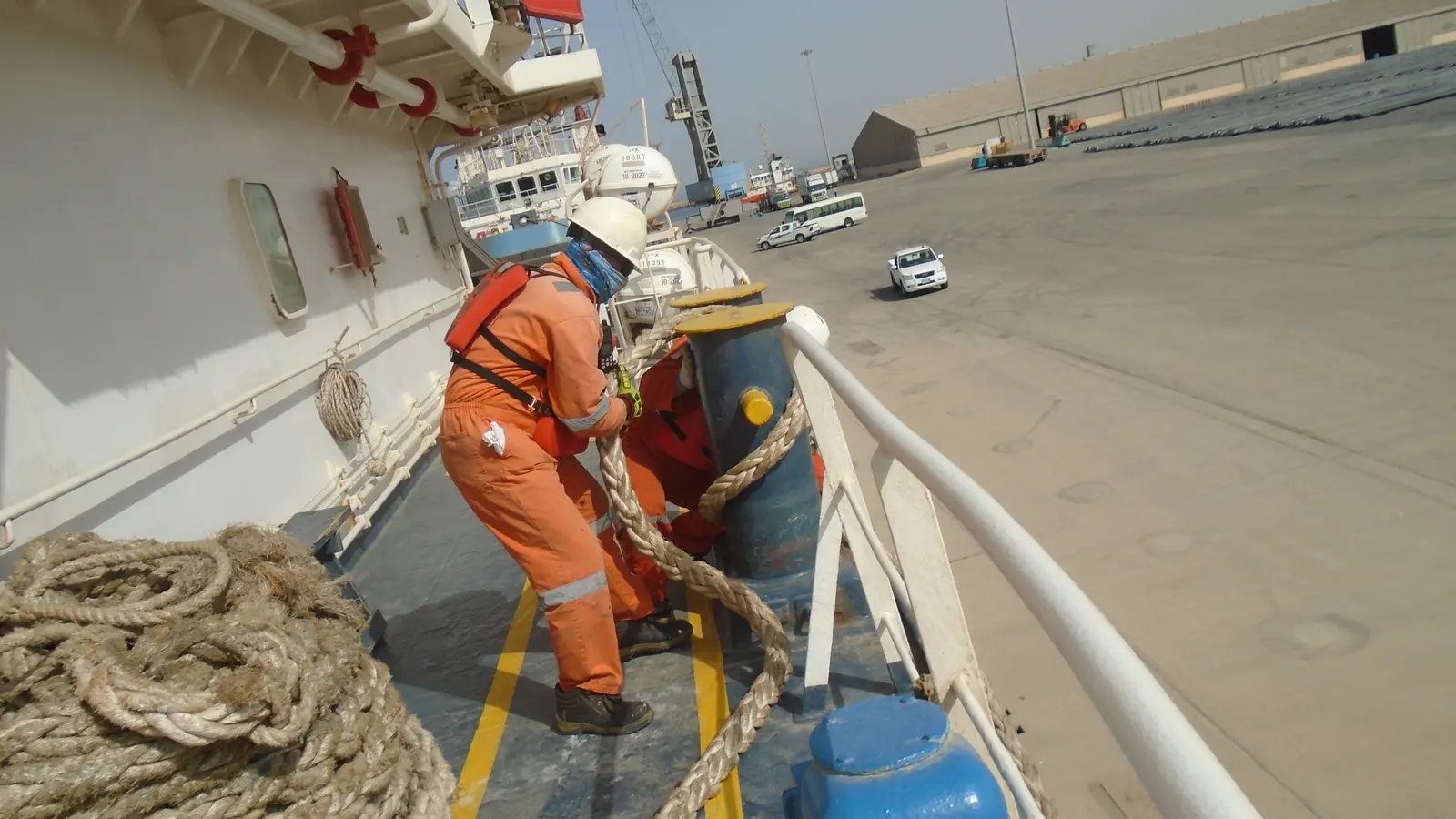
Featured image: Seafarers securing a mooring line on a ship’s bitts, photographed by Ciacho5 via Wikimedia Commons, CC BY-SA 4.0. Cropped and converted to WebP by Tide Signal News; the adapted image is distributed under the same licence.